
 English
  Español
  Deutsch
Content
- 1 What Is a Metallographic Cutting Machine?
- 2 Types of Metallographic Sectioning Equipment
- 3 Cutting Wheels and Blades: The Heart of Metallographic Cut-Off Equipment
- 4 Key Specifications When Selecting Metallographic Sectioning Machines
- 5 Best Practices for Metallographic Sample Cutting: Avoiding Common Errors
- 6 Metallographic Cutting Equipment in Context: The Full Sample Preparation Workflow
What Is a Metallographic Cutting Machine?
A metallographic cutting machine — also called a metallographic sectioning machine, metallographic cut-off machine, or metallographic cutter — is a precision instrument used to section metal, ceramic, composite, or mineral specimens in preparation for microscopic examination. The defining requirement that separates metallographic sectioning equipment from general metalworking saws is minimal damage to the specimen's microstructure at and adjacent to the cut surface: no heat-affected zone, no mechanical deformation, no smearing of soft phases, and no cracking of brittle phases.
Metallographic sample preparation begins with sectioning. Everything that follows — mounting, grinding, polishing, etching, and microscopic examination — depends entirely on the quality of the initial cut. A section produced with excessive heat or pressure introduces artifacts that are indistinguishable from genuine material defects under the microscope, invalidating the analysis. Selecting and operating the correct metallographic cutting equipment for each material class is therefore the foundational skill of laboratory sample preparation.
The metallographic cutter market segments into two principal instrument types — abrasive cut-off machines and precision low-speed saws — each optimized for different material categories and quality requirements. Understanding the capabilities and limitations of each type is essential for any laboratory specifying metal sample preparation equipment.
Types of Metallographic Sectioning Equipment
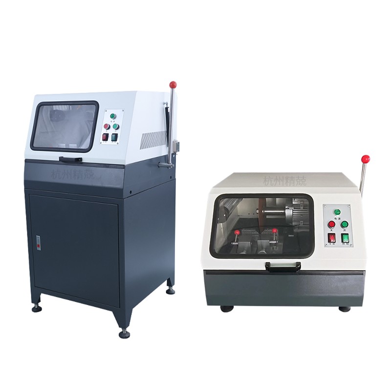
Metallographic Abrasive Cutter (Cut-Off Machine)
The metallographic abrasive cutter — also known as a metallographic cut-off saw, metallurgical cut-off equipment, or sample preparation sectioning saw — uses a thin, rotating abrasive wheel to section specimens by grinding rather than sawing. The wheel is a bonded abrasive disc (aluminum oxide for ferrous materials, silicon carbide for non-ferrous and ceramics) that removes material by abrasion along the cut plane. Wheel diameters typically range from 150 mm to 400 mm, and spindle speeds from 2,000 to 5,000 RPM depending on the machine size and material.
The critical variable in abrasive cut-off machine operation is heat generation at the cutting interface. Abrasive sectioning inherently generates friction heat; if not controlled, this heat raises the specimen temperature above phase transformation or tempering thresholds — altering the very microstructure the cut is intended to expose for analysis. Modern metallographic sectioning machines address this through flood coolant systems that deliver cutting fluid directly to the wheel-specimen interface throughout the cut, keeping specimen temperature below 50–60°C even in long cuts through dense alloy steels.
Metallographic abrasive cutters further divide by their feed mechanism:
- Manual cut-off machines: The operator applies feed force by hand through a pivoting arm. Suitable for soft-to-medium hardness materials and moderate throughput. Lower capital cost, but feed force consistency depends on operator skill.
- Automatic cut-off machines: Feed force is applied by a motorized actuator (electromechanical or pneumatic) with programmable feed rate and force parameters. Automatic sectioning machines deliver more consistent cut quality, enable unattended operation for batch sectioning, and are essential for hard, brittle, or high-value specimens where inconsistent feed would cause wheel loading or specimen fracture.
Metallographic Low-Speed Saw (Precision Sectioning Machine)
The metallographic low-speed saw — also referred to as a precision sectioning machine, metallographic sectioning saw, or metallographic sample preparation machine for delicate specimens — operates at dramatically lower wheel speeds (100–500 RPM) using a diamond wafering blade rather than an abrasive wheel. The combination of slow cutting speed and the extremely thin kerf of a diamond blade (0.1–0.5 mm versus 0.5–1.5 mm for abrasive wheels) generates negligible heat and virtually no mechanical deformation in the specimen.
The low-speed saw applies load through a dead-weight or spring-loaded feed mechanism rather than powered actuators, allowing very light, controlled forces that preserve even the most fragile microstructural features. This makes it the instrument of choice for:
- Electronic components and circuit boards — thin solder joints, intermetallic layers, and copper traces require damage-free sectioning to examine cross-sections without smearing or cracking
- Brittle and porous materials — ceramics, thermal spray coatings, sintered carbides, and geological samples that would fracture under the forces of abrasive sectioning
- Biological and mineralogical specimens — bone, tooth enamel, mineral sections for petrography, and similar heterogeneous materials
- Thin sections for TEM sample preparation — where the starting cut must be made as close as possible to the target region with the minimum possible subsurface damage layer
- Soft metals and coatings — gold, indium, tin, and soft solder alloys that smear catastrophically under abrasive wheel conditions
The tradeoff for this precision is throughput: a low-speed saw may require 15–60 minutes to complete a cut that an abrasive cutter would finish in under two minutes. For high-value or irreplaceable specimens, this time cost is entirely justified; for routine steel bar sectioning in production quality control, it is not.
Cutting Wheels and Blades: The Heart of Metallographic Cut-Off Equipment
Wheel and blade selection is the most critical consumable decision in metallographic sectioning. An incorrect wheel for the material being cut produces excessive heat, rapid wheel wear, and poor cut quality regardless of the machine quality. The correct wheel for the material produces a clean, cool, artifact-free section with acceptable wheel life and cutting speed.
Abrasive Cut-Off Wheels
Abrasive cut-off wheels are specified by abrasive type, bond hardness, and structure (porosity). The general selection rules are:
- Aluminum oxide (Al₂O₃) wheels — for ferrous materials: carbon steels, alloy steels, stainless steels, tool steels, and cast irons. Aluminum oxide is harder than iron and provides efficient cutting without excessive wheel wear in these materials.
- Silicon carbide (SiC) wheels — for non-ferrous materials (aluminum, copper, brass, bronze, titanium, magnesium alloys), ceramics, and refractory materials. Silicon carbide is sharper and cuts with less heat generation in softer, more thermally sensitive non-ferrous alloys.
- Bond hardness: Soft-bonded wheels (grade designation B or C in most systems) are used for hard materials — the bond releases worn abrasive grains quickly, exposing fresh cutting edges and preventing wheel glazing. Hard-bonded wheels (grade E–H) are used for soft materials — the stronger bond retains abrasive grains longer, preventing the wheel from wearing too rapidly in low-resistance materials.
- Reinforced vs. non-reinforced: Laboratory metallographic cut-off wheels are glass-fiber reinforced for safety at the high rotational speeds of sectioning machines. Non-reinforced wheels must never be used on motorized cut-off equipment.
Diamond Wafering Blades for Low-Speed Saws
Diamond wafering blades for precision sectioning machines are specified by diamond concentration, bond type (metal bond, resin bond), and blade thickness. Higher diamond concentration gives longer blade life at higher cost; resin bond blades are more aggressive and faster cutting; metal bond blades are more durable and better suited to hard, dense materials such as cemented carbides and advanced ceramics. Blade thickness selection governs kerf width and material loss — for high-value specimens or when precise feature location is required, thinner blades minimize the material removed at each cut.
| Material Category | Recommended Machine Type | Wheel / Blade Type | Key Risk to Avoid |
|---|---|---|---|
| Carbon and alloy steel | Abrasive cut-off (auto feed) | Al₂O₃, medium bond | Heat-affected zone, tempering of hardened steel |
| Hardened tool steel / HSS | Abrasive cut-off (auto, low force) | Al₂O₃, soft bond | Wheel loading, overheating, specimen cracking |
| Aluminum / copper alloys | Abrasive cut-off | SiC, hard bond | Smearing, wheel clogging |
| Ceramics / carbides | Low-speed saw | Diamond, metal bond | Chipping, fracture along grain boundaries |
| Electronic components / PCBs | Low-speed saw | Diamond, resin bond, thin kerf | Delamination, smeared solder, cracked die |
| Thermal spray coatings | Low-speed saw (after mounting) | Diamond, resin bond | Coating delamination, pullout of splats |
Key Specifications When Selecting Metallographic Sectioning Machines
Specifying metal sample preparation equipment requires matching the machine's performance parameters to the specimen sizes, material types, throughput requirements, and quality standards of the laboratory. The following parameters are the most important evaluation criteria:
Maximum Specimen Size and Clamping Capacity
The specimen vice or clamping system defines the maximum cross-section that can be held securely for cutting. Laboratory metallographic abrasive cutters typically accommodate specimen cross-sections from a few millimeters up to 60–80 mm diameter for bench-top models, and up to 150 mm or larger for floor-standing production-scale sectioning equipment. The clamping system must hold the specimen rigidly without allowing any movement during the cut — any lateral specimen movement while the wheel is in contact produces a curved cut surface and can fracture the abrasive wheel catastrophically.
Wheel or Blade Speed and Variable Speed Control
Abrasive cut-off machines typically operate at fixed spindle speeds in the range of 2,800–3,500 RPM for standard wheel diameters. Variable speed control is advantageous for laboratories cutting diverse material types — lower speeds reduce heat generation in thermally sensitive non-ferrous alloys, while maximum speed may be required for efficient cutting of large-diameter steel sections. Low-speed saws with continuously variable speed (typically 1–500 RPM) provide maximum flexibility for adapting cut parameters to each material and blade specification.
Feed Force Control and Automation
Automatic metallographic sectioning machines control feed force through servo motor or pneumatic actuator systems, with user-programmable force and feed rate settings. Force-controlled feed — where the machine maintains constant contact force regardless of material resistance — is superior to speed-controlled feed for heterogeneous specimens (e.g., composites or weld samples crossing multiple material zones), as it adapts automatically to local material hardness and prevents wheel overload in hard phases. The best automatic metallurgical sample preparation machines combine programmable force profiles with soft-start and end-of-cut detection to minimize wheel wear and specimen damage throughout the cutting cycle.
Coolant System Design
Coolant delivery directly determines specimen temperature during abrasive sectioning. Effective coolant systems on metallographic cut-off equipment deliver 3–10 liters per minute of cutting fluid through nozzles positioned on both sides of the wheel at the cut interface, ensuring the entire kerf zone is flooded throughout the cut. Recirculating coolant systems with settling tanks and filtration extend coolant life and prevent swarf accumulation in the cutting zone. For laboratories concerned about coolant contamination of specimens (important for subsequent chemical analysis), clean-water coolant systems or dry sectioning with specially formulated low-heat wheels are alternatives.
Vibration and Rigidity
Machine rigidity — the resistance of the frame, spindle, and clamping system to deflection under cutting forces — directly affects cut surface flatness and parallelism. Vibration during cutting introduces waviness into the cut face that must be removed by additional grinding steps, wasting specimen material and preparation time. Cast iron or welded steel machine frames, precision spindle bearings with defined runout tolerances, and anti-vibration base mounts characterize high-quality metallographic sectioning equipment. Published spindle runout specifications of ≤0.01 mm TIR distinguish precision instruments from production-grade cut-off machines.
Best Practices for Metallographic Sample Cutting: Avoiding Common Errors
Even with the correct machine and wheel selection, poor operating practice introduces artifacts that compromise metallographic analysis. The following practices reflect accumulated laboratory experience across metallurgical sample preparation:
- Never dry-cut with abrasive wheels. A single dry cut — even a brief one — can raise surface temperatures above 200°C in steel, causing tempering of martensitic structures and introducing a white etching layer detectable under optical microscopy. Always verify coolant flow before starting the cut.
- Mount fragile or porous specimens before sectioning. Thermal spray coatings, foam materials, and porous sintered compacts should be vacuum-impregnated with epoxy resin before sectioning to prevent pullout and collapse of pores during cutting. The resin supports the microstructure throughout all subsequent preparation steps.
- Allow sufficient distance from features of interest. The cut face itself contains some degree of damage — even with the best sectioning practice. Section at least 1–2 mm away from a critical feature (weld fusion line, coating interface, crack tip) and remove the damage layer by grinding before the feature is exposed for examination.
- Use the appropriate feed force for the material. Excessive feed force in abrasive sectioning — particularly in hard, brittle materials — causes wheel deflection, curved cuts, and thermal spikes. Start with the minimum force that achieves steady cutting progress and increase only if wheel glazing (loss of cutting action) is observed.
- Dress abrasive wheels regularly. A glazed or loaded abrasive wheel cuts slowly, generates excess heat, and can fracture under increased feed force. Dress the wheel with a single-point diamond dresser or dressing stick at the first signs of reduced cutting efficiency.
- Record sectioning parameters for each specimen. In failure analysis and research contexts, documenting the machine type, wheel specification, coolant type, feed force, and cut duration for each specimen creates an audit trail that allows any sectioning artifact to be identified and distinguished from genuine material defects during the reporting phase.
Metallographic Cutting Equipment in Context: The Full Sample Preparation Workflow
Metallographic sectioning equipment is the first step in a defined preparation sequence. Understanding where sectioning fits within the broader workflow clarifies why cut quality has such disproportionate influence on final analytical results.
- Sectioning — metallographic cut-off machine or low-speed saw produces the initial section. Cut quality determines how much material must be removed in subsequent grinding to reach an undamaged surface.
- Mounting — the section is encapsulated in thermosetting or cold-cure resin (epoxy, phenolic, acrylic) to create a standardized, handleable puck for subsequent steps and to support specimen edges and fragile features during polishing.
- Grinding — successive passes on grinding papers (SiC or diamond-bonded) of decreasing grit size remove the damage layer from sectioning and establish a flat, planar surface. The depth of grinding required is directly proportional to the severity of sectioning damage — high-quality sectioning reduces grinding time by 30–50% compared to poorly controlled sectioning.
- Polishing — diamond suspension or colloidal silica polishing on cloth laps removes remaining grinding scratches to produce a mirror finish free of deformation. Final surface roughness on polished metallographic specimens is typically Ra <0.01 µm.
- Etching — chemical or electrolytic etching reveals grain boundaries, phase boundaries, and microstructural features by selectively attacking different phases and orientations. The most commonly used etchant for carbon and low-alloy steels is 2–4% Nital (nitric acid in ethanol); austenitic stainless steels use Kalling's reagent or electrolytic etching in oxalic acid.
- Examination — optical microscopy, scanning electron microscopy (SEM), electron backscatter diffraction (EBSD), energy-dispersive X-ray spectroscopy (EDS), and hardness testing are performed on the prepared surface to characterize the material's microstructure, phase composition, grain size, inclusion content, coating thickness, and defect morphology.
The investment in high-quality metallographic cutting equipment and correct wheel selection pays compounding returns across every subsequent preparation step — reducing grinding time, preserving specimen geometry, protecting fragile features, and ensuring that the microstructure observed under the microscope is the true material microstructure, not a preparation artifact.