
 English
  Español
  Deutsch
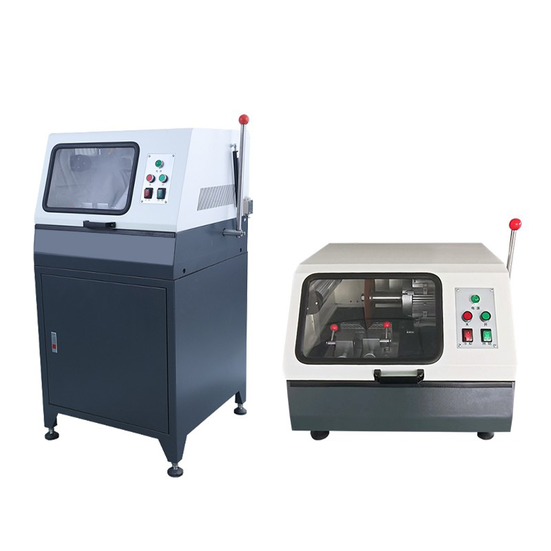
A metallographic cutting machine is the first and most consequential step in sample preparation — a poor cut introduces deformation, heat damage, or smearing that no amount of polishing can fully remove afterward. The difference between a usable cross-section and a ruined sample usually comes down to three controllable factors: blade selection, cutting speed, and coolant delivery.
Content
- 1 Why Cutting Quality Determines the Outcome of the Entire Sample Prep Process
- 2 Matching Cutting Wheel Type to Material Hardness
- 3 Cutting Speed, Feed Rate, and Their Role in Heat Generation
- 4 Coolant Delivery Systems and Why Flow Rate Matters as Much as Coolant Type
- 5 Sample Clamping and Fixturing for Consistent, Repeatable Cuts
Why Cutting Quality Determines the Outcome of the Entire Sample Prep Process
Metallographic sectioning is fundamentally different from rough cutting — the goal is to remove material with minimal mechanical deformation and minimal heat input, since both can alter the microstructure being studied. A cut that introduces a deformation layer deeper than what subsequent grinding and polishing steps can remove will leave artifacts visible under the microscope, leading to misleading conclusions about grain structure, hardness, or phase distribution.
This is why metallographic cutting machines are built around abrasive cutoff wheels rather than friction saws or band saws — abrasive cutting removes material through a high-speed grinding action that, when properly controlled, produces a smooth, low-deformation surface requiring less subsequent grinding to reach the area of interest.
Matching Cutting Wheel Type to Material Hardness
Abrasive cutoff wheels are typically classified by their abrasive grain (aluminum oxide or silicon carbide) and bond hardness. The general rule is counterintuitive to many newcomers: harder materials require softer-bonded wheels, because a softer bond releases dull abrasive grains faster, continuously exposing fresh sharp grains rather than letting the wheel glaze over and generate excess heat.
| Material | Abrasive Type | Bond Hardness |
|---|---|---|
| Soft non-ferrous (Al, Cu, brass) | Silicon carbide (SiC) | Hard bond |
| Mild and low-carbon steel | Aluminum oxide (Al2O3) | Medium bond |
| Hardened steel, tool steel | Aluminum oxide (Al2O3) | Soft bond |
| Ceramics, composites | Diamond or CBN | Resin or metal bond |
For very hard or brittle materials such as sintered carbides, ceramics, and electronic components, diamond or CBN (cubic boron nitride) wheels are required, as conventional aluminum oxide or silicon carbide wheels wear too quickly and generate excessive heat.
Cutting Speed, Feed Rate, and Their Role in Heat Generation
Most laboratory metallographic cutters operate wheel speeds in the range of 1,500–5,000 RPM, with the optimal speed depending on wheel diameter and material. A larger wheel diameter generally requires a lower RPM to maintain the same peripheral cutting speed, which is the parameter that actually governs cutting action and heat generation.
- Higher feed rates reduce total cutting time but increase the risk of localized overheating and burning, particularly on heat-sensitive materials
- Lower feed rates produce a cleaner cut with less deformation but extend cycle time and can increase wheel wear if too slow causes glazing
- Automatic feed control, available on most precision cutting machines, maintains constant force on the wheel regardless of operator input — important for reproducibility across multiple samples
- Pulsed or oscillating cutting modes reduce continuous heat buildup for heat-sensitive alloys, by briefly retracting the wheel at intervals to allow coolant to flush the cut zone
Coolant Delivery Systems and Why Flow Rate Matters as Much as Coolant Type
Coolant serves two purposes in metallographic cutting: removing heat from the cut zone and flushing away abrasive debris that would otherwise clog the wheel and reduce cutting efficiency. Water-soluble coolants with corrosion inhibitors are standard for ferrous materials, while specialized coolants are used for materials sensitive to water exposure, such as magnesium alloys, which can react with water-based fluids.
Flow rate and nozzle positioning are often underestimated factors. A coolant stream that doesn't directly target the wheel-workpiece interface provides minimal cooling benefit regardless of total volume — most precision cutters use dual nozzles positioned on either side of the wheel to ensure coverage throughout the cut, especially as the wheel progresses deeper into thicker samples.
Sample Clamping and Fixturing for Consistent, Repeatable Cuts
Inconsistent clamping is a common but overlooked source of cutting defects. A sample that shifts even slightly during cutting can cause wheel deflection, leading to a wavy or angled cut surface that complicates mounting and grinding. Vise-style clamps with adjustable jaw inserts accommodate irregular shapes, while V-block fixtures are preferred for cylindrical samples like rod or tube cross-sections to prevent rotation under cutting force.
For small or fragile samples — thin sheet metal, wires, or brittle ceramics — secondary support fixtures or sacrificial backing material are often used to prevent the sample from cracking or being thrown from the clamp as the wheel exits the cut. Maximum cutting capacity, typically specified as the largest sample diameter or cross-section a machine can accommodate, should be checked against typical sample sizes since exceeding it forces multiple repositioning cuts that increase the chance of misalignment between cut surfaces.