
 English
  Español
  Deutsch
Content
- 1 Rockwell, Brinell, and Vickers: Understanding the Three Major Hardness Testing Methods
- 2 Vickers to Rockwell Hardness Conversion: How It Works and Where It Falls Short
- 3 Metallurgical Sample Preparation: The Foundation of Reliable Hardness Data
- 4 Hardness Testing Tools and Their Selection Criteria
- 5 Carbon Steel Weld Inspection: Hardness Testing in the Heat-Affected Zone
- 6 Precision Cutter Machines in Metallographic Sample Preparation
Rockwell, Brinell, and Vickers: Understanding the Three Major Hardness Testing Methods
Hardness testing measures a material's resistance to permanent deformation under a defined load. The three dominant methods — Rockwell, Brinell, and Vickers — each use a different indenter geometry, load range, and measurement approach, making them suited to different materials and applications.
Rockwell hardness (HR) applies a minor preload followed by a major load, then measures the net depth of indentation. The result is read directly from the dial or digital display without any optical measurement, making it the fastest method for production-floor testing. It uses multiple scales — HRC for hard steels, HRB for softer metals, HRA for carbides — each defined by a specific indenter and load combination.
Brinell hardness (HB or HBW) presses a hardened steel or tungsten carbide ball into the surface under a fixed load, typically 3,000 kgf for steel and cast iron. The indentation diameter is measured optically, and the HB number is calculated from the applied load divided by the curved surface area of the indent. Because the indent is relatively large, Brinell averaging is less sensitive to local microstructural variation, making it preferred for coarse-grained materials like castings and forgings.
Vickers hardness (HV) uses a square-based diamond pyramid indenter with a 136° face angle at loads ranging from under 1 gf (micro-Vickers) to 120 kgf (macro-Vickers). Both diagonals of the square indent are measured and averaged. The HV number is calculated using the load divided by the contact surface area of the impression. Vickers is the most versatile method: it applies to thin coatings, case-hardened layers, weld heat-affected zones, and bulk material alike, all on a single continuous scale.
| Method | Indenter | Measurement | Best For |
|---|---|---|---|
| Rockwell | Diamond cone or steel ball | Depth of indent | Fast production testing of hardened steel |
| Brinell | Tungsten carbide ball (ø1–10 mm) | Indent diameter (optical) | Castings, forgings, coarse-grained alloys |
| Vickers | Diamond pyramid (136°) | Diagonal length (optical) | Thin coatings, welds, micro-hardness |
Vickers to Rockwell Hardness Conversion: How It Works and Where It Falls Short
Converting Vickers hardness to Rockwell hardness — and vice versa — is a frequent requirement when engineering drawings specify one scale but available test equipment uses another. The most widely accepted reference is ASTM E140, which provides standardized conversion tables for various ferrous and non-ferrous materials.
For hardened steel in the range commonly used in tooling and structural applications, the approximate relationships are:
- HV 940 ≈ HRC 68 (near the upper limit of the Rockwell C scale)
- HV 800 ≈ HRC 65
- HV 600 ≈ HRC 57
- HV 400 ≈ HRC 41
- HV 200 ≈ HRB 93 (transition to B scale for softer materials)
- HV 100 ≈ HRB 56
These conversions carry an important caveat: they are material-specific. The elastic-to-plastic deformation ratio differs between carbon steel, stainless steel, aluminum alloys, and titanium. A Vickers-to-Rockwell conversion valid for carbon steel will produce error when applied to austenitic stainless or a nickel superalloy. ASTM E140 provides separate columns for different material families precisely for this reason.
An additional limitation arises at the extremes: the Rockwell C scale is only reliable between HRC 20 and HRC 70. Values outside this range should be measured on a more appropriate scale (HRA for very hard materials above HRC 70, HRB for softer materials below HRC 20) or reported directly in HV without conversion.
For weld inspection and quality-controlled environments, converted values should always be flagged as estimated. Direct measurement on the intended scale is the only way to obtain a traceable, specification-compliant result.
Metallurgical Sample Preparation: The Foundation of Reliable Hardness Data
A hardness test is only as accurate as the surface it measures. Poor sample preparation introduces error that no instrument calibration can correct. This is especially true for Vickers and Brinell methods, where the measurement is optical and surface reflectivity directly affects diagonal or diameter reading accuracy.
Sectioning
The first step is producing a flat, representative cross-section. A precision cutter machine (also called an abrasive or diamond cut-off saw) is used to section the workpiece with minimal heat input and mechanical deformation. Abusive cutting — using a dull blade, excessive feed rate, or inadequate coolant — causes a deformed or heat-affected surface layer that artificially elevates or depresses hardness readings. For metallurgical-grade cuts, diamond wafering blades with continuous water cooling are standard for hard steels and carbides, while resin-bonded aluminum oxide cut-off wheels suit softer structural metals.
Mounting and Grinding
After sectioning, samples are typically mounted in thermosetting or cold-cure epoxy resin to allow safe handling during grinding and polishing. Edge retention mounts are specified when near-surface hardness gradients — such as case depths or coating interfaces — must be measured without edge rounding.
Grinding follows a sequence from coarser to finer SiC abrasive papers (typically 120 → 320 → 600 → 1200 grit), with the sample rotated 90° between each step to remove scratches from the prior direction. Each stage must fully remove deformation introduced by the previous one.
Polishing
Final polishing uses 3 µm and 1 µm diamond suspension on napped cloths, producing a scratch-free mirror finish. For Vickers micro-hardness, a 0.25 µm colloidal silica finish is often specified to minimize surface-reflectivity errors when measuring small indentations at low loads. The polished surface must be free of relief, smear, and pitting before testing begins.
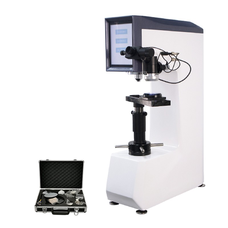
Hardness Testing Tools and Their Selection Criteria
Selecting the right hardness testing tool involves matching the instrument's load range and indenter type to the material thickness, expected hardness range, and required spatial resolution.
- Benchtop Rockwell testers — the standard choice for incoming inspection and heat treatment verification of bulk steel components. Load application is motorized and consistent, and modern digital models store test records for SPC integration. The Rockwell method cannot be used on thin stock (typically under 1 mm for HRC) because the indent depth approaches the material thickness, violating the minimum thickness rule.
- Vickers / Knoop microhardness testers — used for thin foils, electroplated coatings, diffusion-hardened surfaces, and individual phases in a microstructure. Load range is typically 1 gf to 1 kgf. An integrated optical microscope images the indent for diagonal measurement, often with automated image analysis for reduced operator variability.
- Portable rebound (Leeb) hardness testers — suited for large, installed components that cannot be brought to a laboratory. A spring-driven impact body strikes the surface; the ratio of rebound to impact velocity gives the Leeb value (HL), which is then converted to HRC, HB, or HV. Accuracy depends on surface finish, mass, and geometry of the workpiece.
- Ultrasonic contact impedance (UCI) testers — use a Vickers diamond on a vibrating rod; the frequency shift upon contact correlates with hardness. UCI instruments are particularly useful for measuring thin case-hardened layers and coatings in situ without surface damage visible to the naked eye.
Regardless of instrument type, regular calibration against certified reference blocks (traceable to national standards such as NIST or PTB) is required to maintain measurement confidence. Reference blocks should span the expected hardness range of production parts.
Carbon Steel Weld Inspection: Hardness Testing in the Heat-Affected Zone
Hardness traverses across welds are among the most critical applications of Vickers testing in structural fabrication. When carbon steel is welded, the heat-affected zone (HAZ) undergoes rapid thermal cycling. In steels with sufficient carbon equivalent (CE), this can produce martensite — a hard, brittle microstructure that raises HAZ hardness significantly above the base metal and increases susceptibility to hydrogen-induced cracking (HIC).
Industry acceptance criteria commonly limit HAZ hardness to a maximum of 350 HV10 for general structural steel weldments (per EN ISO 15614-1 and AWS D1.1 guidance), and to 250–300 HV10 for offshore, sour service, or high-toughness applications. Exceeding these thresholds is a disqualifying condition requiring review of preheat, interpass temperature, and welding procedure.
A standard weld hardness traverse involves a series of Vickers indentations at defined spacing — typically 0.5 mm or 1 mm apart — running from the weld metal through the fusion line, across the HAZ, and into the unaffected base metal. The traverse is conducted on a metallographically prepared cross-section, etched with 2–5% Nital to reveal the fusion boundaries before indentation placement. Key measurement locations include the coarse-grained HAZ immediately adjacent to the fusion line, where martensite formation is most likely.
For root passes and narrow-gap welds, micro-Vickers at HV1 or HV0.5 may be required to achieve adequate spatial resolution within the HAZ, which can be as narrow as 0.2–0.5 mm in some high-heat-input processes. The choice of test load directly affects the indent size and therefore the minimum measurable zone width — HV10 produces an indent approximately 0.3–0.4 mm across at 300 HV, while HV1 reduces this to roughly 0.1 mm.
Precision Cutter Machines in Metallographic Sample Preparation
A precision cutter machine is the entry point of every metallographic workflow. Its primary function is to produce a flat, damage-minimized cross-section that accurately represents the area of interest — whether that is a weld HAZ, a case-hardened surface, or a coating interface.
Two main categories exist in laboratory use:
- Abrasive cut-off saws — use consumable resin-bonded wheels and are suited for production throughput. Wheel selection (aluminum oxide for steel and cast iron, silicon carbide for non-ferrous, CBN for hardened tool steel) and coolant flow rate are the primary process parameters. Burn marks or blueing on the cut surface indicate excessive heat and require slower feed or fresh wheel selection.
- Diamond wafering saws — use metal- or resin-bonded diamond blades at low speed with oil coolant. They produce the lowest deformation layer (typically under 5 µm) and are essential for brittle ceramics, electronic components, and samples where the intact microstructure must be preserved within microns of the cut surface.
Key specifications when selecting a precision cutter for hardness test preparation include maximum workpiece diameter, chuck clamping force, blade RPM range, and coolant delivery method. Automated feed control — where the saw advances at a constant force rather than a fixed rate — significantly reduces operator-to-operator variability and extends blade life.
For weld inspection samples in particular, the cutter must accommodate irregular geometries (T-joints, pipe sections, overlay cladding) with stable fixturing. Unstable clamping causes vibration-induced chatter marks that propagate deep into the sample, creating a deformed layer that cannot be fully removed in subsequent grinding steps without excessive stock removal.