
 English
  Español
  Deutsch
Metallographic cutting machines, inlay machines, and grinding and polishing machines are the three sequential pieces of equipment that form a complete metallographic sample preparation workflow — and the quality of every downstream microstructure analysis depends directly on how well each stage is executed. In brief: the cutting machine sections the specimen from bulk material without thermal or mechanical damage; the inlay machine encapsulates the specimen in resin for safe handling and edge retention; and the grinding and polishing machine progressively removes surface material to produce a scratch-free, deformation-free mirror surface ready for microscopic examination and etching. Selecting and operating each machine correctly is not a matter of preference — it determines whether the microstructural features revealed under the microscope reflect the true material condition or are artifacts of poor preparation.
Content
- 1 The Three-Stage Metallographic Sample Preparation Process
- 2 Metallographic Cutting Machine: Precision Sectioning Without Damage
- 3 Metallographic Inlay Machine: Mounting for Precision and Edge Retention
- 4 Metallographic Grinding and Polishing Machine: Achieving the Mirror Surface
- 5 Selecting Equipment for Different Laboratory Needs
- 6 Common Preparation Defects and Their Root Causes
- 7 Maintenance and Consumable Management for Metallographic Equipment
The Three-Stage Metallographic Sample Preparation Process
Metallographic analysis — the examination of a metal's microstructure to assess grain size, phase distribution, inclusion content, heat treatment response, weld quality, and defect morphology — requires a specimen surface of exceptional flatness and freedom from preparation artifacts. Achieving this demands a disciplined three-stage preparation sequence, with each stage addressing specific sources of surface damage introduced by the previous step.
- Stage 1 — Sectioning: A metallographic cutting machine extracts a representative section from the bulk sample with minimal heat generation and mechanical deformation.
- Stage 2 — Mounting (Inlay): A metallographic inlay machine encapsulates the cut specimen in a mounting resin — either hot compression or cold resin — to create a standardized, handleable puck that protects edges and enables automated grinding and polishing.
- Stage 3 — Grinding and Polishing: A metallographic grinding and polishing machine removes the deformed layer from cutting and mounting, progressing through abrasive papers and diamond/silica suspension polishing steps to produce the final mirror surface.
Errors at any stage propagate forward — a thermally damaged cut surface cannot be fully corrected by polishing alone, and an improperly mounted specimen will rock during grinding, producing a convex surface (called "rounding") that makes edge features unexaminable. This is why equipment selection and operating parameters at each stage receive serious engineering attention in materials laboratories and quality control departments worldwide.
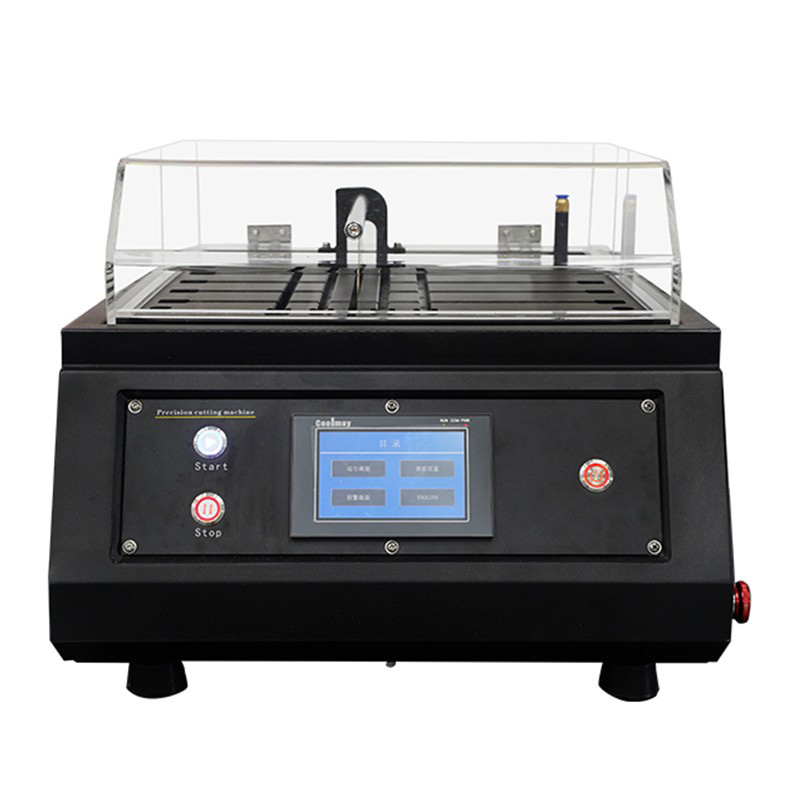
Metallographic Cutting Machine: Precision Sectioning Without Damage
The metallographic cutting machine — also called a metallographic sectioning machine or abrasive cutter — uses a thin rotating abrasive wheel to section a metal specimen from bulk material. Unlike industrial cutting tools, a metallographic cutter is engineered specifically to minimize the depth of the mechanically and thermally affected zone (the "damage zone") introduced at the cut surface, because this damage zone must later be removed by grinding. The thinner and shallower the damage zone, the less grinding is required and the faster the total preparation cycle.
Types of Metallographic Cutting Machines
- Abrasive wheel cutters (precision cutters): Use resin-bonded abrasive wheels — typically aluminum oxide (Al₂O₃) for ferrous materials or silicon carbide (SiC) for non-ferrous and ceramics — rotating at 3,000 to 5,000 rpm. Continuous water-based coolant flooding is essential to prevent thermal damage. Precision abrasive cutters can section specimens with a damage depth of less than 50µm under correct parameters.
- Diamond wire saws: Use a continuously moving wire impregnated with diamond abrasive, cutting by abrasion rather than impact. Generate virtually no heat and produce damage zones as thin as 5 to 20µm. Used for brittle materials (ceramics, semiconductors, electronic components) and precious or irreplaceable specimens where material loss must be minimized.
- Slow-speed precision saws: Use a hub-mounted diamond blade rotating at very low speed (typically 300 to 1,000 rpm) with minimal applied force. Produce the least damage of any cutting method but are slow — suited for small, delicate, or high-value specimens where preparation quality outweighs throughput.
Key Specifications to Evaluate When Selecting a Cutting Machine
| Specification | Abrasive Wheel Cutter | Slow-Speed Diamond Saw | Diamond Wire Saw |
|---|---|---|---|
| Wheel/Blade Speed | 3,000–5,000 rpm | 300–1,000 rpm | Variable (wire speed) |
| Damage Zone Depth | 20–100µm | 5–30µm | 5–20µm |
| Max Sample Diameter | Up to 160mm+ | Up to 75mm | Up to 300mm+ |
| Material Suitability | Metals, composites | All materials (delicate) | Ceramics, brittle materials |
| Throughput | High | Low | Low–Medium |
Coolant and Feed Force Control
Coolant flow is the single most important operating parameter in abrasive wheel cutting. Insufficient coolant allows the cut surface temperature to rise above the material's tempering temperature — for hardened steel, as low as 150°C to 200°C — causing microstructural changes (tempering, re-austenitization, or martensite transformation) that make the cut surface non-representative of the bulk. Quality metallographic cutters provide coolant flow rates of 3 to 8 liters per minute directed precisely at the wheel-specimen interface.
Automatic feed force control — where the machine senses cutting resistance and adjusts the feed rate to maintain constant force — prevents the operator from applying excessive pressure that would overheat the wheel and specimen. Machines with programmable force control (typically 10N to 300N adjustable range) consistently produce better cut surfaces than manually fed units, particularly for high-throughput laboratory environments.
Metallographic Inlay Machine: Mounting for Precision and Edge Retention
After sectioning, most specimens must be mounted — encapsulated in a resin puck — before grinding and polishing. Mounting serves several critical functions: it provides a standardized, flat, parallel geometry that fits automated grinding heads; it supports fragile or porous specimens and prevents edge breakout; it protects edges and near-surface features (coatings, case-hardened layers, nitrided zones) from rounding during polishing; and it enables safe handling of sharp-edged specimens and small pieces that would otherwise be impossible to grip consistently.
Hot Compression Mounting
A hot compression metallographic inlay machine (mounting press) places the specimen and resin powder in a heated cylinder, applies hydraulic pressure and heat to cure the resin around the specimen, then ejects the completed mount. The entire cycle takes 8 to 15 minutes depending on resin type and mount diameter. Standard mount diameters are 25mm, 30mm, 32mm, and 40mm.
Common hot mounting resins include:
- Phenolic resin (Bakelite): The most widely used hot mounting resin. Cycle temperature 150°C to 180°C, pressure 200 to 300 bar. Produces hard, dimensionally stable mounts with good edge retention. Not suitable for temperature-sensitive specimens (soft solders, low-melting alloys, polymers).
- Conductive resin (graphite or copper-filled): Essential for SEM (scanning electron microscopy) examination where the mount must be electrically conductive to prevent charge buildup. Slightly lower hardness than phenolic but adequate for most grinding sequences.
- Diallyl phthalate (DAP) resin: Lower curing temperature (120°C to 150°C) than phenolic, suitable for slightly more temperature-sensitive specimens. Produces transparent mounts that allow specimen orientation to be verified visually.
Cold Mounting
Cold mounting uses two-component liquid resin systems (epoxy, acrylic, or polyester) poured around the specimen in a mold at room temperature without a press. No specialized inlay machine is required — mounting is performed in disposable or reusable molds — making cold mounting the preferred choice for temperature-sensitive specimens, porous materials (where vacuum impregnation is needed to fill voids before mounting), and laboratories without a hot press.
Epoxy cold mounts offer the best edge retention and lowest shrinkage of cold mounting materials, but require curing times of 8 to 24 hours at room temperature (reduced to 1 to 4 hours with gentle heating to 40°C to 60°C). Acrylic cold mounts cure in 10 to 20 minutes but generate significant exothermic heat during cure — sometimes enough to alter heat-treated microstructures in small or thin specimens — and exhibit higher shrinkage, leading to gap formation between resin and specimen edge.
Vacuum Impregnation Units
Vacuum impregnation is a specialized cold mounting technique used for porous specimens — sintered metals, thermal spray coatings, cast irons with graphite, corroded materials, or geological samples. The specimen is placed in a chamber, vacuum is applied to evacuate air from the pores, liquid epoxy is admitted under vacuum, and atmospheric pressure is then restored to drive the resin into the pores before curing. This fills all porosity with resin, preventing pore pullout during polishing — which would otherwise appear as artificial "holes" in the microstructure. Some metallographic inlay machines incorporate an integrated vacuum impregnation function within the press cylinder for this purpose.
Metallographic Grinding and Polishing Machine: Achieving the Mirror Surface
The metallographic grinding and polishing machine is where the actual surface preparation is completed. Starting from the rough surface left by cutting and mounting, the machine progressively removes material through a series of decreasing abrasive sizes — each step eliminating the scratches from the previous step — until the surface is free of visible deformation under the microscope. A properly prepared metallographic surface has a scratch depth of less than 0.02µm (20nm) and a deformed subsurface layer shallow enough to be removed by light final polishing.
Machine Types: Manual, Semi-Automatic, and Fully Automatic
- Manual grinding and polishing machines: A single rotating platen (wheel) on which the operator manually holds and moves specimens. Simple and low-cost but highly operator-dependent — results vary with applied force, specimen orientation, and operator consistency. Suitable for low-volume or training laboratories.
- Semi-automatic machines: A motorized specimen holder head applies controlled downward force on a group of specimens (typically 3 to 6 mounts) while the platen rotates. The operator loads specimens, sets force and time, and the machine runs the step automatically. Dramatically improves reproducibility over manual preparation.
- Fully automatic machines: Robotic specimen handling, automatic abrasive paper or disc changing, automatic dispensing of grinding and polishing suspensions, and programmable multi-step sequences. Capable of preparing 6 to 9 specimens per cycle with complete reproducibility. Used in high-throughput production quality control laboratories and research facilities where preparation consistency across operators and shifts is critical.
The Grinding and Polishing Sequence
A standard preparation sequence for a medium-hardness steel (e.g., 45 HRC) involves the following stages:
- Plane grinding: SiC abrasive paper, P120 to P320 grit, or a fixed-abrasive grinding disc. Removes the damage layer from cutting and establishes a flat, parallel surface across all specimens in the holder. Typically run for 1 to 3 minutes at 150–300 rpm with 20–30N force per specimen.
- Fine grinding: SiC papers P600, P800, P1200 (or equivalent diamond grinding discs). Each step removes scratches from the previous grit size. Water-lubricated SiC paper is the most common consumable; diamond grinding discs are faster and more consistent but cost more per step.
- Diamond polishing: Cloth-covered platens with diamond suspension or paste — typically 9µm, then 3µm, then 1µm diamond. Removes fine grinding scratches and produces a high-reflectance surface with minimal deformation. Lubricant selection (water-based, alcohol-based, or oil-based) is matched to the material being prepared.
- Final polishing (oxide polishing): Colloidal silica suspension (OPS, typically 0.04µm particle size) on a short-nap cloth. Combines fine mechanical abrasion with mild chemical activity that removes the last residual deformation layer, producing the scratch-free mirror surface required for EBSD analysis and high-resolution etching.
Critical Machine Parameters: Force, Speed, and Rotation Mode
Three machine parameters have the greatest influence on preparation quality and efficiency:
- Applied force per specimen: Too little force produces slow material removal and rounded edges; too much causes excessive scratching and deformation. Most modern machines allow force setting in the range of 5N to 50N per specimen, with different materials requiring different optimal forces (soft metals like aluminum at 10–15N, hardened steels at 20–30N).
- Platen speed: Typically 150 to 300 rpm for grinding, 100 to 150 rpm for polishing. Higher speeds increase material removal rate but also increase heat generation and specimen holder wear; polishing steps benefit from lower speeds that allow the polishing suspension to remain active at the specimen surface.
- Contra-rotation (contra mode): In this mode, the specimen holder head rotates in the opposite direction to the platen. This ensures that each specimen receives equal exposure across the full abrasive surface and eliminates the directionality of scratches, producing more uniform material removal across a batch of specimens. Contra-rotation is the standard mode for semi-automatic and automatic machines used in production metallography.
Selecting Equipment for Different Laboratory Needs
| Laboratory Type | Recommended Cutting Machine | Recommended Inlay Machine | Recommended Grinding/Polishing |
|---|---|---|---|
| University / Teaching Lab | Manual abrasive cutter | Manual hot press (25–30mm) | Manual single-platen machine |
| R&D / Materials Research | Precision abrasive cutter + slow-speed saw | Auto hot press + vacuum impregnation unit | Semi-auto machine with force control |
| Production QC (metals, automotive) | High-throughput auto abrasive cutter | Fast-cycle auto hot press (40mm, <8 min) | Fully automatic robotic polisher |
| Electronics / Semiconductor Failure Analysis | Diamond wire saw or slow-speed precision saw | Epoxy cold mount with vacuum impregnation | Semi-auto with OPS final polish capability |
| Ceramics / Advanced Materials | Diamond wire saw or SiC-wheel cutter | Epoxy cold mount (low shrinkage) | Auto machine with diamond disc grinding |
Common Preparation Defects and Their Root Causes
Understanding what can go wrong at each stage — and which machine or process parameter caused it — is essential for troubleshooting preparation quality in a working laboratory:
- Thermal damage at cut surface (burn marks, white layer, tempered zones): Caused by insufficient coolant flow or excessive feed force during cutting. Solution: increase coolant flow rate; reduce feed force; replace worn cutting wheel.
- Edge rounding (loss of near-surface features): Caused by resin hardness mismatch (resin too soft relative to specimen), insufficient mount cure, or incorrect polishing force. Solution: use harder mounting resin (phenolic over acrylic); add conductive filler to increase hardness; reduce polishing force at final stages.
- Scratches remaining after polishing (comet tails): Caused by abrasive contamination from a previous grit step carried over to a finer polishing step. Solution: implement rigorous between-step cleaning (ultrasonic cleaning or thorough rinsing); use separate polishing cloths per diamond size.
- Pitting or pullout of second-phase particles: Caused by excessive final polishing time with colloidal silica on soft matrices, or incorrect pH of polishing suspension. Solution: reduce OPS polishing time; verify suspension pH is appropriate for the material system.
- Non-planar (convex or wedge-shaped) surface: Caused by non-parallel specimen-to-holder seating in the grinding head, or inconsistent specimen height within a batch holder. Solution: ensure mounts are within ±0.05mm height tolerance before loading; use a pre-grind step to equalize specimen heights.
Maintenance and Consumable Management for Metallographic Equipment
The operational cost of a metallographic preparation setup is dominated not by machine depreciation but by consumable expenditure — cutting wheels, mounting resins, abrasive papers, polishing cloths, and diamond suspensions. Managing these consumables correctly is as important as selecting the right equipment:
- Cutting wheel replacement: Abrasive wheels must be replaced when the wheel diameter has decreased by more than 30% from new, or when burning or loading (metal smearing on the wheel face) is observed. Using a worn wheel increases thermal damage to specimens even with adequate coolant.
- Abrasive paper change frequency: SiC paper at P320 grit typically remains effective for 3 to 5 specimens per sheet when used with a 30mm mount diameter. Continuing beyond this produces inconsistent removal rates and longer step times that negate the cost savings from paper reuse.
- Coolant maintenance for cutting machines: Water-based cutting coolants develop bacterial contamination and pH drift over time, leading to corrosion of freshly cut specimen surfaces. Replace coolant completely every 2 to 4 weeks in regular use; monitor pH (target 8.5 to 9.5) and add biocide as needed.
- Hot press cylinder maintenance: The mounting cylinder should be cleaned of resin residue after every 20 to 50 cycles and the piston o-rings inspected for wear. A worn o-ring allows resin to flash behind the piston, increasing ejection force and eventually jamming the press.